Basic tutorial:Build Slab Model
· (updated ) · DFT · 5
This note introduces the basic workflow for building and optimizing VASP slab models. It explains how to choose the surface size, number of layers, vacuum thickness, and dipole corrections for reliable surface calculations.
1. Slab Models
The general workflow for studying surface-reaction mechanisms is: (1) optimize the bulk structure to obtain the equilibrium lattice constants; and (2) construct a slab model based on the optimized bulk structure.
A slab model is used because, in heterogeneous catalysis, reactions occur on the catalyst surface, which is the interface between the gas or liquid phase and the solid phase. To simulate a solid surface, we need a structure that is periodic in two dimensions to represent the solid surface, while the third dimension is nonperiodic and represents the gas or liquid phase. In practice, however, periodic boundary conditions are usually also applied along the third dimension. The periodic images are separated by an empty region, known as the vacuum layer. Care must be taken to avoid interactions between the two periodic images along the third dimension. In other words, the electron density should approach zero across the vacuum region so that one slab does not affect its neighboring image. This can be achieved as follows:
- Increase the vacuum-layer thickness to a suitable value. An excessively thick vacuum layer slows the calculation. For surface-reaction calculations, a vacuum thickness of 15 Å is generally sufficient.
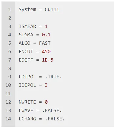
- In VASP, add
LDIPOL = .TRUE.andIDIPOL = 3(the z direction) to reduce the effect of the dipole moment caused by the asymmetry between the two slab surfaces.
For surface structures, pay attention to the following points:
- Surface size in the *x*–*y* plane: This affects the coverage of adsorbates, the size of the system, and the computational cost. A different surface size requires a correspondingly appropriate k-point mesh.
- Surface orientation: Common choices include (111), (110), and (100). The choice depends on the research objective because different facets have different surface energies, surface structures, and catalytic activities.
- Number of slab layers:
- More layers mean more atoms and a larger system size along the z direction, which also increases the computational cost.
- The number of layers that need to be relaxed must be selected.
- The number of layers can affect calculated properties such as the surface energy.
- Different facets require different numbers of layers. More open surfaces generally require more layers.
- The appropriate number of layers should be tested for the specific system.
- Slab symmetry: Slab models can be either symmetric, with equivalent top and bottom surfaces, or asymmetric. Symmetric slabs often require many layers and therefore produce larger systems. Asymmetric slabs are smaller, but they introduce a dipole-moment effect. In that case,
LDIPOLandIDIPOLshould be included to reduce this effect.
1.1 Constructing a Surface Model
Structural optimization of bulk Cu
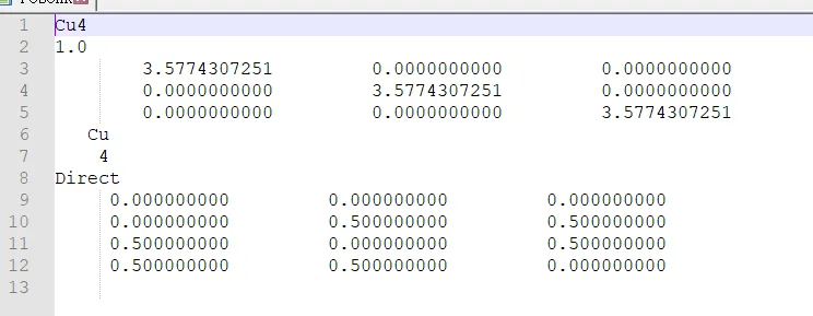
1. Construct the POSCAR file
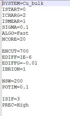
Prepare the INCAR file
Note:
LREALis set toAutohere to maintain consistency with the subsequent surface-energy calculations. The appropriate value ofLREALshould be selected according to the number of atoms and the requirements of subsequent calculations. Energies calculated withLREAL = .FALSE.should not be compared with energies calculated withLREAL = ONor.TRUE..- For bulk-material calculations, the same
ENCUT,ENAUG,PREC,LREAL, andROPTvalues are often used throughout the entire workflow so that the results can be used consistently in subsequent calculations of other properties.
A general guideline for structural optimization is to avoid using the default energy cutoff for volume relaxations whenever possible. Manually set ENCUT in the INCAR file to increase the basis-set cutoff, or use the alternative procedure recommended below. This can completely avoid volume relaxation. If volume relaxation is the only practical and feasible option, use the following stepwise procedure to minimize the error:
1.3 Building a Slab Model in Materials Studio
- After importing the unit cell, open the Surface Box interface and select Build → Surface → Cleave Surface. Enter the desired Miller index in Cleave Plane (hkl), such as (111). Adjust the depth to obtain the required number of atomic layers by changing Thickness.
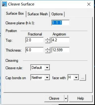
- In the Options interface, change Orientation Standard so that the U vector is aligned with the x axis and V lies in the x–y plane.
- In Surface Mesh → Surface Vectors, modify the vectors of the slab model, and then select Cleave to create the surface. In this example, the (111) surface is selected. The surface termination and slab thickness can also be selected by adjusting Top and Thickness in Surface Box.
- Add the vacuum layer by selecting Build → Crystals → Build Vacuum Slab. Set Vacuum Orientation to C to place the vacuum layer along the z direction. The vacuum thickness can be changed using Vacuum Thickness, for example, to 10 Å, 15 Å, or a larger value. The appropriate value can be determined from the preceding calculations. Finally, select Build to complete construction of the slab model.
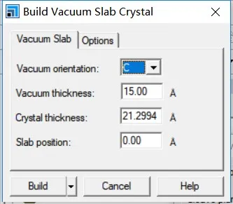
- The vacuum layer can be aligned with the z axis through Lattice Parameters → Advanced → Re-orient to Standard.
[!NOTE] Why use these settings in Materials Studio?
The Orientation Standard option should be set so that the U vector is aligned with the x axis and V lies in the x–y plane, rather than setting V along the x axis and U in the x–y plane.
>
The reason is that Materials Studio defines an ordered coordinate system for the surface vectors.
>
For a cleaved surface, $U$ and $V$ are the two in-plane lattice vectors. The surface normal is obtained from their cross product:
>
$\mathbf{C}\propto \mathbf{U}\times\mathbf{V}$
>
The standard choice is therefore:
>
$\mathbf U=(U,\,0,\,0)$
>
$\mathbf V=(Vx,\,Vy,\,0)$
>
This makes:
>
- $U$ lie along the global x axis;
- both $U$ and $V$ lie in the x–y surface plane;
- $\mathbf U\times\mathbf V$ point along $+z$;
- the vacuum direction, or the $C$ direction, align with z.
>
>
If you choose $V$ along x and $U$ in the x–y plane:
>
$\mathbf V=(V,\,0,\,0)$
>
$\mathbf U=(Ux,\,Uy,\,0)$
>
then:
>
$\mathbf U\times\mathbf V$
>
usually points along $-z$, because the order of the vectors has been exchanged. This can reverse:
>
- the surface normal;
- the top and bottom surfaces;
- the direction of the vacuum;
- the sign of the $C$ lattice vector;
- the interpretation of adsorbate height and dipole direction.
>
There is also a geometric reason: for a nonorthogonal surface, $U$ and $V$ are not parallel, so both cannot be placed along the x axis. One vector defines the x direction, and the second vector determines the remaining rotation within the x–y plane.
>
Thus, “U along x, V in xy” is a coordinate convention, not a physical law. You can exchange $U$ and $V$, but you must check that the resulting $C$ vector still points in the desired surface-normal direction. For VASP surface calculations, the standard choice is safer because it gives:
>
$a,\,b \parallel \text{surface}, \qquad c \parallel \text{surface normal/vacuum}$
1.4 Single-Point Calculation for p(1 × 1) Cu(111)
1.4.1 Slab-model calculation
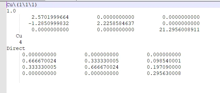
1. Construct the slab model
A primitive cell is used here, whereas a conventional cell is used in the preceding section. Face-centered cubic metals can be modeled using a primitive cell, but cleaving a surface model from a primitive cell can cause problems for other types of systems.
A. After the bulk calculation is complete, convert CONTCAR to a CIF file using VESTA, and then import the CIF file into Materials Studio.
B. Select Build → Symmetry → Primitive Cell.
C. Select Build → Surfaces → Cleave Surface.
D. Obtain the p(1 × 1) Cu(111) surface.
K-points
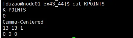
Why is only one k point used along the z direction? If the vacuum region is sufficiently thick, the electron density gradually vanishes at a short distance from the slab edge. This means that a single k point along the $b_3$ direction is sufficient to obtain accurate results.
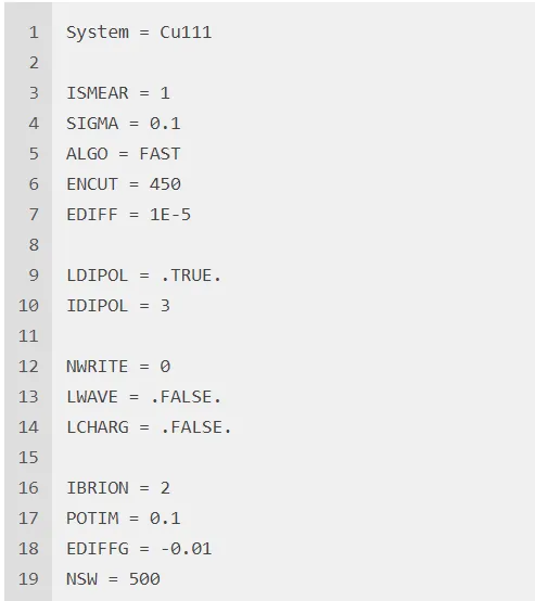
INCAR
Single-point calculation results

1.4.2 Slab-model optimization
1. Modify the slab model
The reason for this modification is that, in a slab model, some atoms are fixed to represent the bulk while other atoms are allowed to relax to represent the surface. In general, the top two atomic layers are allowed to relax, while the atoms below them are fixed. The physical interpretation is that, under realistic conditions, the catalyst bulk is treated as unchanged, and only surface atoms participate in the catalytic reaction.
Key modification points:
- Change the relevant line to
Selective Dynamics. VASP recognizes onlySors. - Add
ForTafter each atomic coordinate to indicate whether the atom is fixed or allowed to move. Because each coordinate has three components, x, y, and z, threeForTflags are required. This allows an atom to move in one direction while remaining fixed in the other directions.
How to modify the file
In this example:
- Add
Selective Dynamicsusing the commandsed -i '7a Selective Dynamics' POSCAR. - Lines 10 and 11 contain the coordinates of the bottom two atomic layers. Append
F F Fusingsed -i '10,11s/$/ F F F/g' POSCAR. - Append
T T Tto the end of lines 12 and 13 usingsed -i '12,13s/$/ T T T/g' POSCAR.
INCAR settings